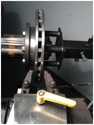
When the cut is complete on the first side and the lathe is shut off by the stop cam, carefully remove the lathe from the vehicle by loosening the drawbar. Use caution as to not crash the cutting tips into any parts of the vehicle as you remove the lathe.
Unless the rotor is completely captured in place, either install at least two nuts on the rotor you've just matched on the first side, or index the rotor to the hub with the crayon from the tool box and remove rotor to make sure it won't fall on the floor when you start the machine on the opposite side. If you don't take this step then you will undo the perfect rotor/hub match you just created.
Now rotate the clutch knob counter clockwise just until the stop cam is no longer in contact with the micro-switch. Next, open both tool arms enough so they will clear the rotor on the second side that has yet to be cut. Remove the adapter and re-install on the second side carefully following all cleaning procedures mentioned previously.
Loosen the disc-lock lever on the trolley and rotate the lathe so the cutting arms will feed in where the caliper was, and you select a position that will allow enough room for the chip deflector. Attach the lathe and follow all instructions as the same as the first side for the machining process. The second side should take you even less time as the cutting head and stop cam are already set up, and you know how much material to remove.